Initial comment: "I'm having trouble making sense of this."
Now it's: "Resolved. see the part at the end.""
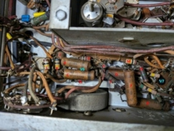
Here is where I started. Objective: Change T3 under caps D and F (center).
The green circled terminals are B+ (A, top, left) and the junction of the red wire from T3, R23 and C36 (Z, middle).
The red wire definitely goes to Z.


The blue wire definitely goes to V6, pin 8.

The green wire definitely goes to the two diodes in V7 (pins 4 and 5) and the gimmick capacitor.

The black wire definitely goes to the junction of R24 and R70 (Y, top right).

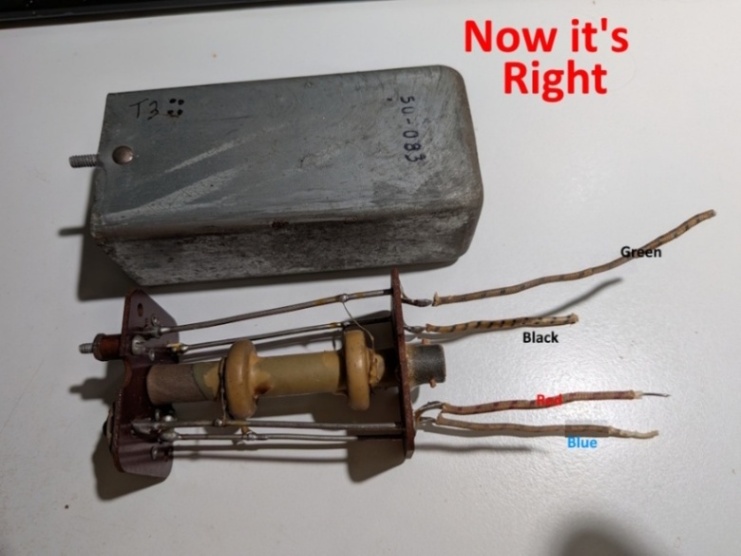
T3 from another radio. I haven't messed with it. The lower coil (on the right in the pic) has the blue and
the black wires. The upper coil has the red and green.

My 1st attempt at rewiring T3.

My 2nd attempt at rewiring T3. I switched blue and green. Note that the thing is rotated 90 degrees clockwise in the 2nd picture.
The lower coil has blue and black wires, upper coil has red and green.

My current best guess at the schematic for the T3 area.

The schematic shows the 4 colors with blue and black paired and red and green paired as per the transformer windings. The original schematic doesn't have anywhere near this amount of detail. The problem is that the black wire definitely went to the junction of R70 and R24 and the red wire definitely went to the junction of R23 and C36.
This does not make sense.
"But wait! There's more..."
Of the five radios I've examined:
T3 from the 3rd radio is completely different from the others.
The wires come out of the can in the proper position to agree with the wire connections noted above:


The 50C136 part fits the this radio but that's not what was in it. And you can see this part of the radio has not been disturbed since day 1.
This also does not make sense. How did this ever work? It was able to pick up one AM station from 16 miles away but that's it.
A friend sent this. His drawing shows the wire colors as my transformer is currently wired but the connections for
green and black reversed. The net effect of this is that the 'positive' (if you will) end of one coil is now
facing the 'negative' end of the other. Or perhaps it's the other way 'round. I don't think it makes any difference
and I'm not going to pursue it any further.

This caused me to take another look at what I was using as a "gold standard" namely
I took more pictures concentrating on the blue and green wires:
This is what I had labeled green above. On very close examination, there's a blue thread left.


This is what I had labeled blue above. With close examination again, there's a green thread still there.


Now my "gold standard" is:
Now my schematic is: (which is what it was before all this started.)

New lesson learned: Trust nothing.
Page: /0_Need_help/Need_help.shtml
Last modified: Sunday, 26 Apr 2026