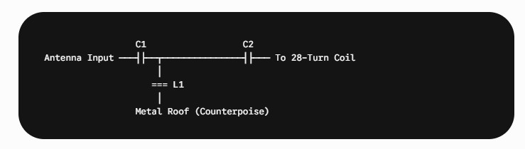
Since modifying the physical winding structure of your homebrew coil is off-limits, replacing those ineffective microfarad capacitors on the rotary switch with a functional RF network is the perfect strategy.
Because you have an excellent selection of small inductors in the $\mu\text{H}$ and $\text{mH}$ range, you can transform that "useless" rotary switch into a powerful front-end conditioning tool for the SX-28.
Here are the three best ways to utilize that 4-position switch to dramatically improve your real-world listening situation.
## Option 1: The 500 kHz High-Pass Filter (The AM Broadcast Band Blocker)
If you want to spend time listening to the lower shortwave bands on the SX-28 (like Band 2 from $1.6$ to $3.0\text{ MHz}$ or the 80-meter ham band), a **$500 KHz High-Pass Filter (HPF)** is a brilliant addition.
Your 35-foot wire and metal roof form a massive collector. Strong, local AM broadcast stations ($550\text{--}1600 KHz) can easily overload the SX-28ΓÇÖs front-end mixer tube when you are trying to listen to weak shortwave signals. A high-pass filter acts as an electrical dam that completely blocks everything below $500 KHz.
### How to implement it on the switch:
You can use a simple, passive 3-element $LC$ **constant-k high-pass filter** layout. You can configure the switch so that:
* **Position 4:** Straight through (No filter - full AM reception). * **Position 3:** The $500 KHz HPF engaged inline with the 28-turn primary.
To calculate a standard $500 KHz high-pass filter matching a nominal $300\,\Omega$ antenna system, you would use two series capacitors and one center shunt inductor:

When engaged, this will attenuate longwave and VLF utility noise completely, keeping the front end of the radio quiet and linear.
---
## Option 2: The Adjustable Multi-Band Notch Filter (The Local Blowtorch Eliminator)
If there is one specific local AM station in your area that is so strong it bleeds across the dial or causes desensitization, you can turn the switch positions into **Series Resonant Trap Filters (Notch Filters)**.
A capacitor and an inductor placed in *series* present a near-zero impedance path at their exact resonant frequency ($f_r = \frac{1}{2\pi\sqrt{LC}}$). If you wire this combination across the input (from the long wire to the metal roof), it will completely swallow that specific frequency and dump it to the roof counterpoise before it ever enters the 28-turn coil.
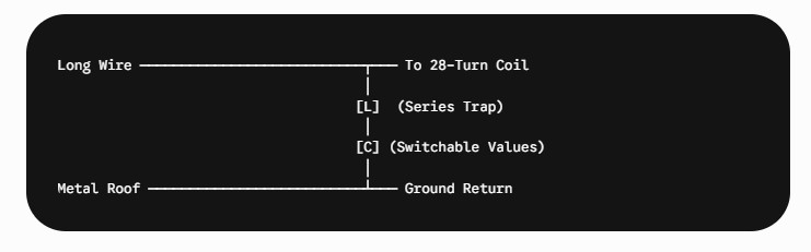
### How to use your parts bin:
Pick a fixed inductor from your selection (for example, a **$100\,\mu\text{H}$** inductor). By using different small picofarad capacitors on the rotary switch, you can notch out different offending frequencies:
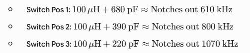
This is highly effective if you have a local "blowtorch" station ruining your AM band DXing.
## Option 3: True Antenna Tuning Capacitors (The Correct Scale)
If you want to keep the original concept of the rotary switchΓÇöwhich was meant to introduce variable capacitive reactance to alter the antenna's electrical sizeΓÇöyou simply need to drop the capacitor values down by **three orders of magnitude**.
Instead of the original microfarad values, replace them with low-loss **Silver Mica or Ceramic Disc capacitors in the picofarad (pF) range**:

Swapping out the original components for these picofarad values will immediately make the knob highly functional. You will physically see the S-meter peak and valley as you switch through the positions, giving you a true passive pre-selector peak control right on the front of your antenna console.
Which approach appeals to you most for your listening postΓÇöblocking local AM blowtorches, filtering out VLF noise, or getting the original reactance-tuning design working on the correct picofarad scale?
Page: /1_need_help/Gemini_23/Gemini_23.shtml
Last modified: Tuesday, 21 Jul 2026