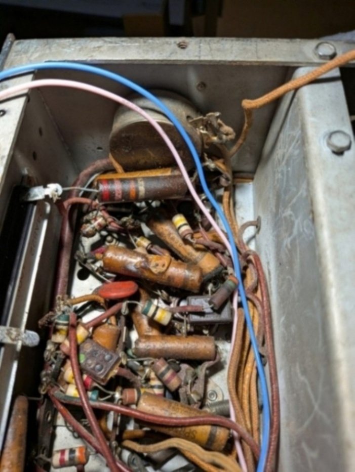
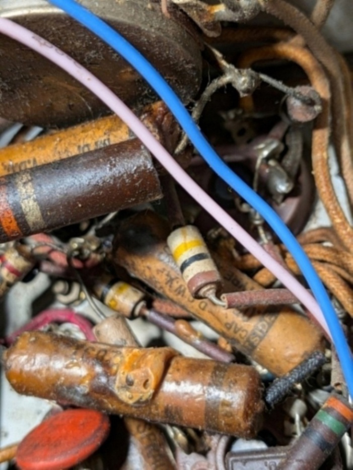
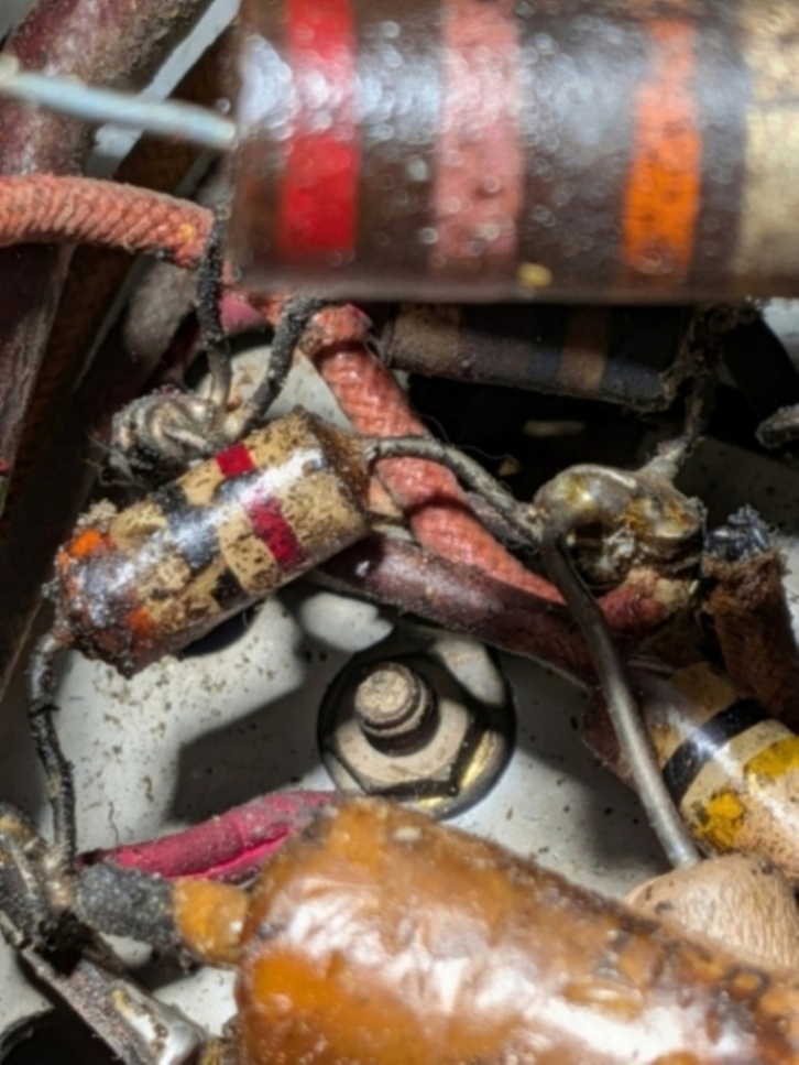
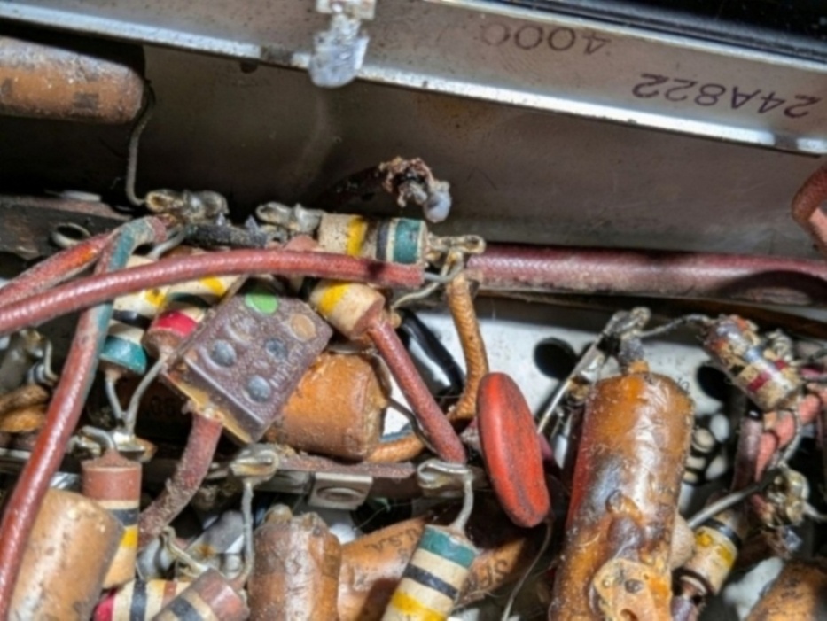
The circuitry next to the back wall of the chassis.
There are two areas of concern: just under the S meter pot (which doesn't work) and just under
the centertap of the screen voltage resistor1 (R31 and R32).
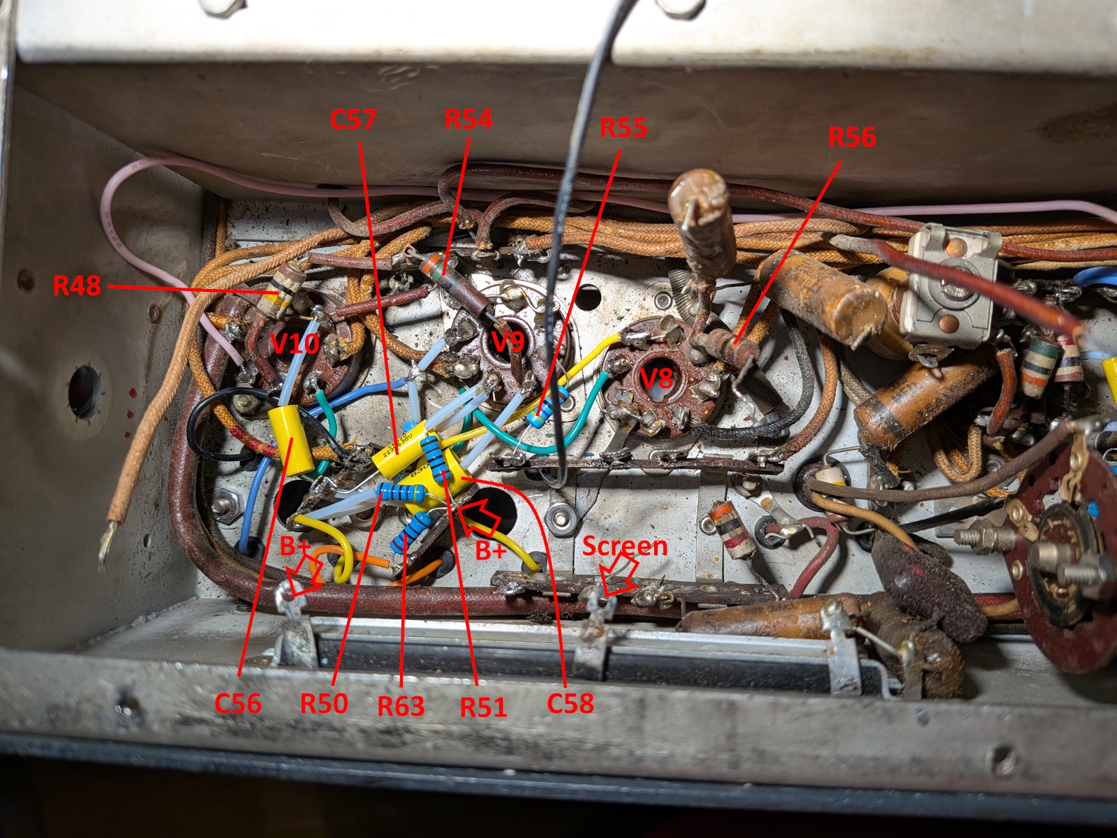
Decided the first thing to do is ID parts:
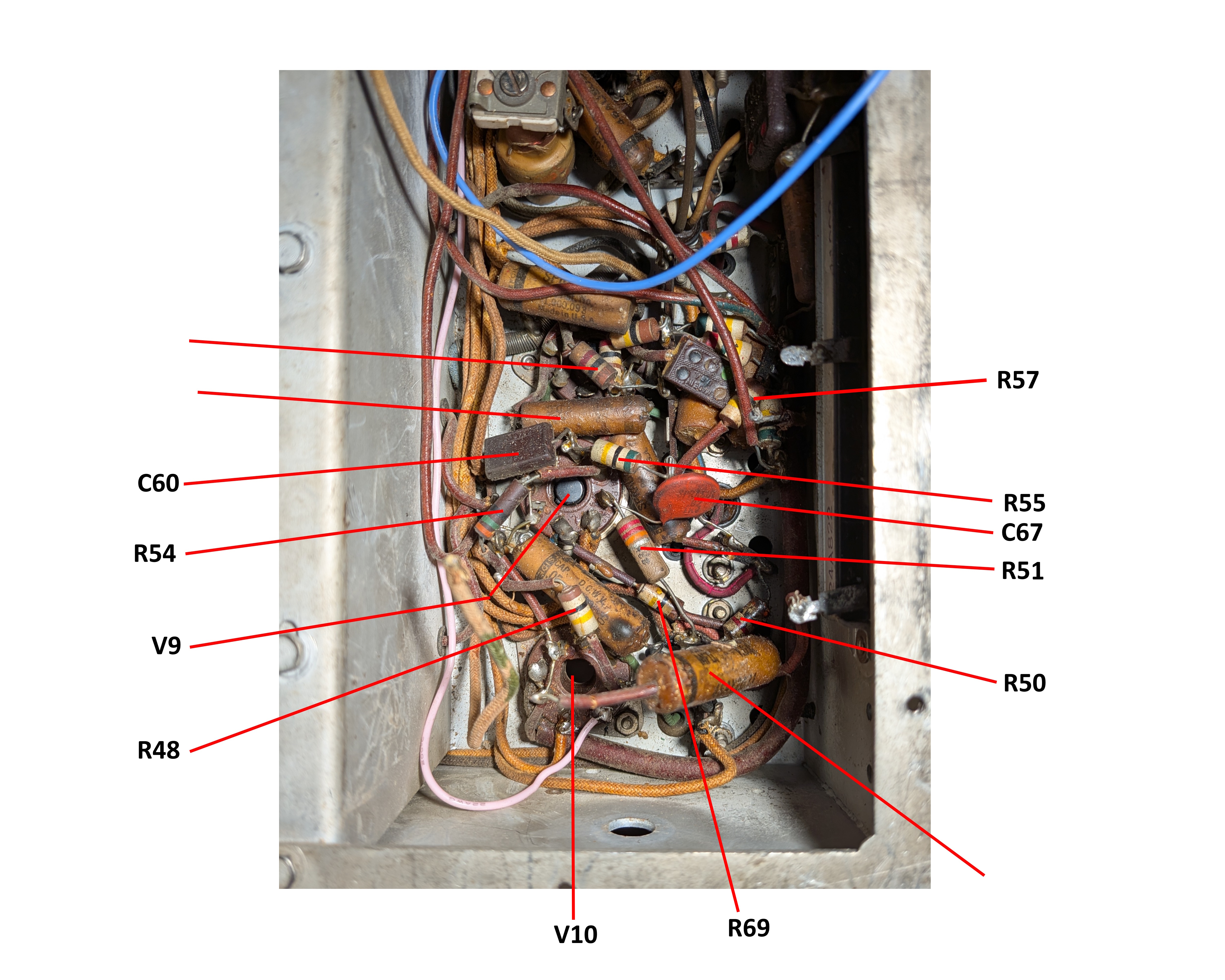
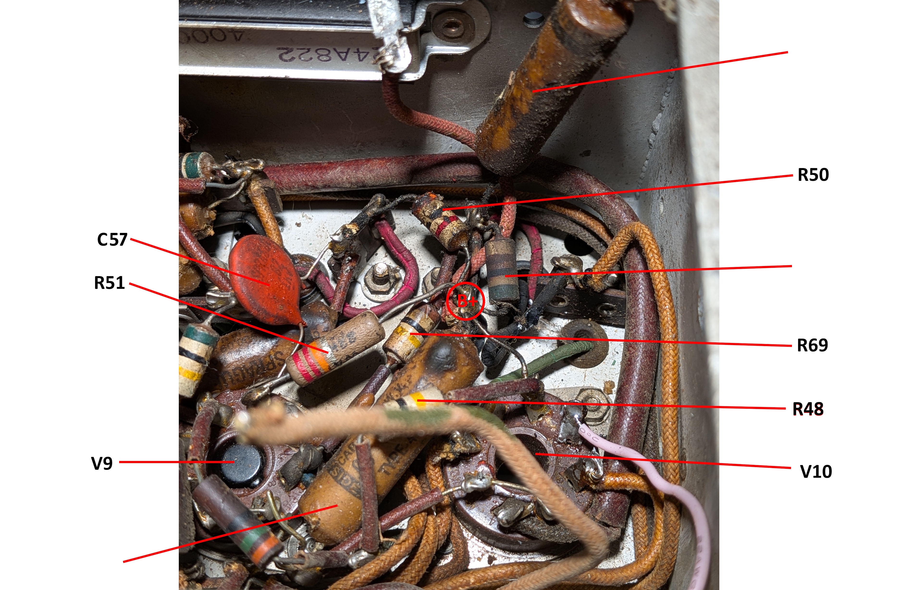
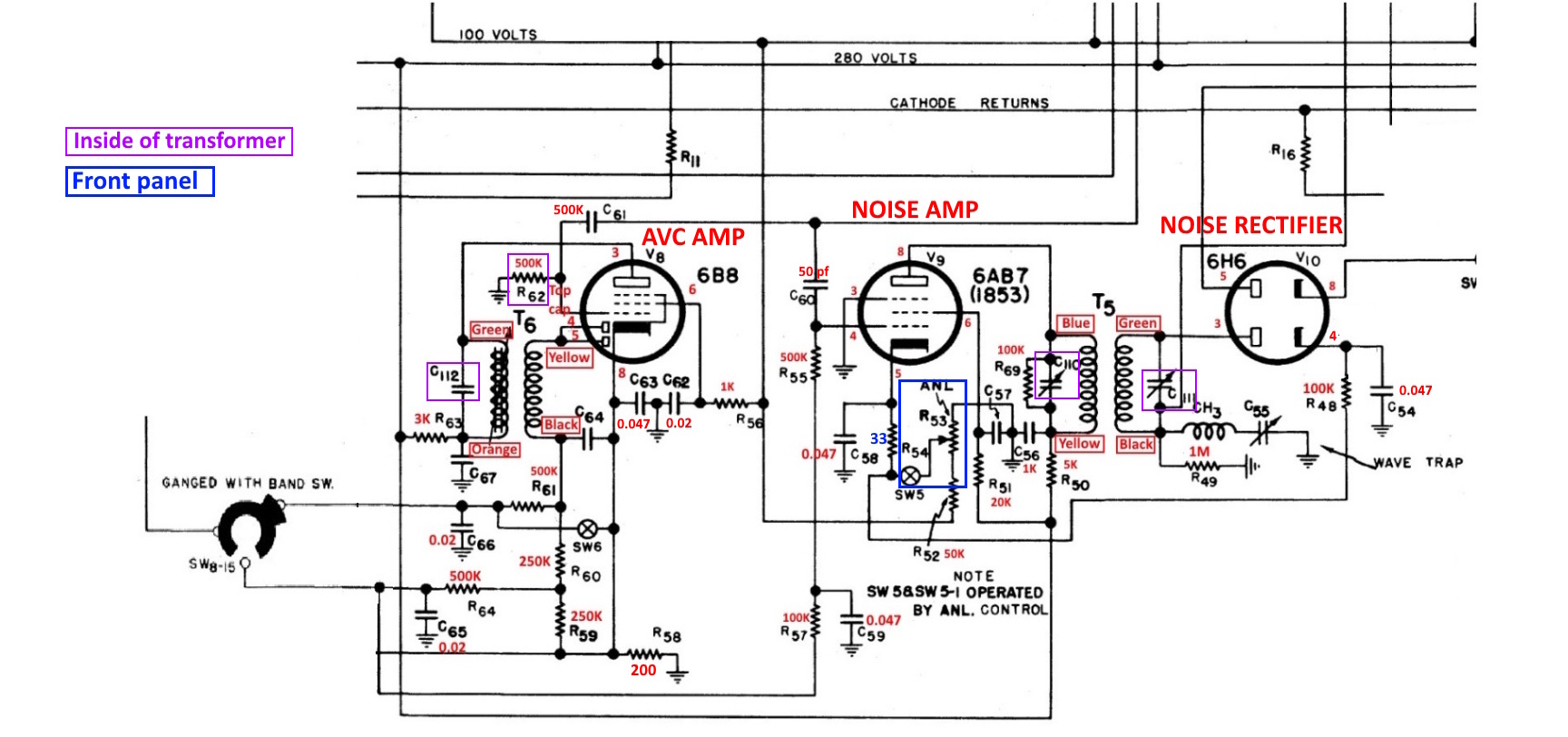
A doctored up schematic of the area. The colors are my colors for T5. The only difference from the transformer in this
radio is the red wire. Mine new silicone wire is yellow and marked as such on the schematic. Yellow was probably my best guess
while looking at what was once a red wire.
Removed most of the stuff including the transformers since the PVC insulation was falling off the wire.
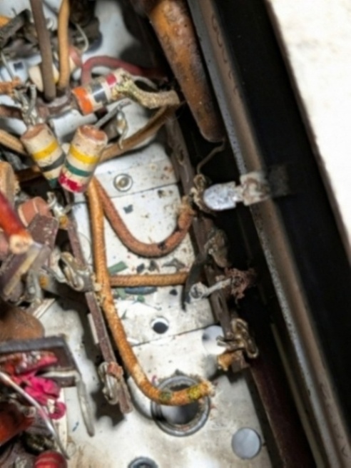
Months pass...
Finally, May 27th, started on this again. Reinstalled T5 and T6.
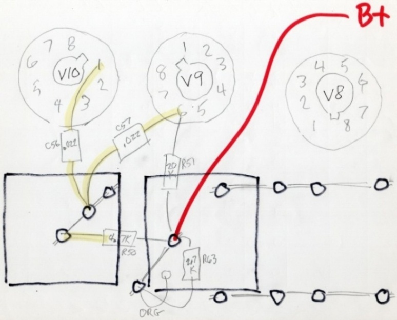
First planning drawing. Completed 5/28/2026 with much pain. Need to make sure you pick the correct value of R before spending a half
hour bent over working in a corner with surgical clamps. As it is, the blue wire from T5 was too short and I wasn't about to
remove it and rewire it. Kludge time.
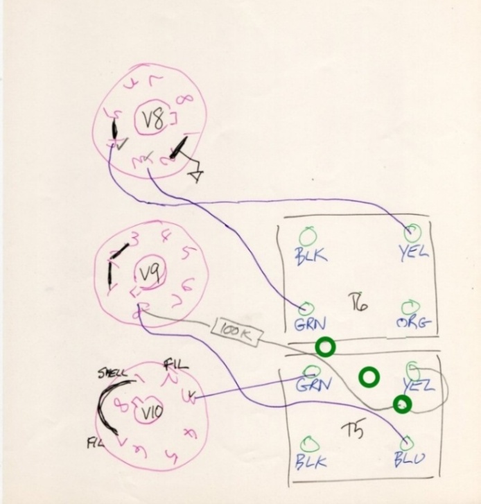
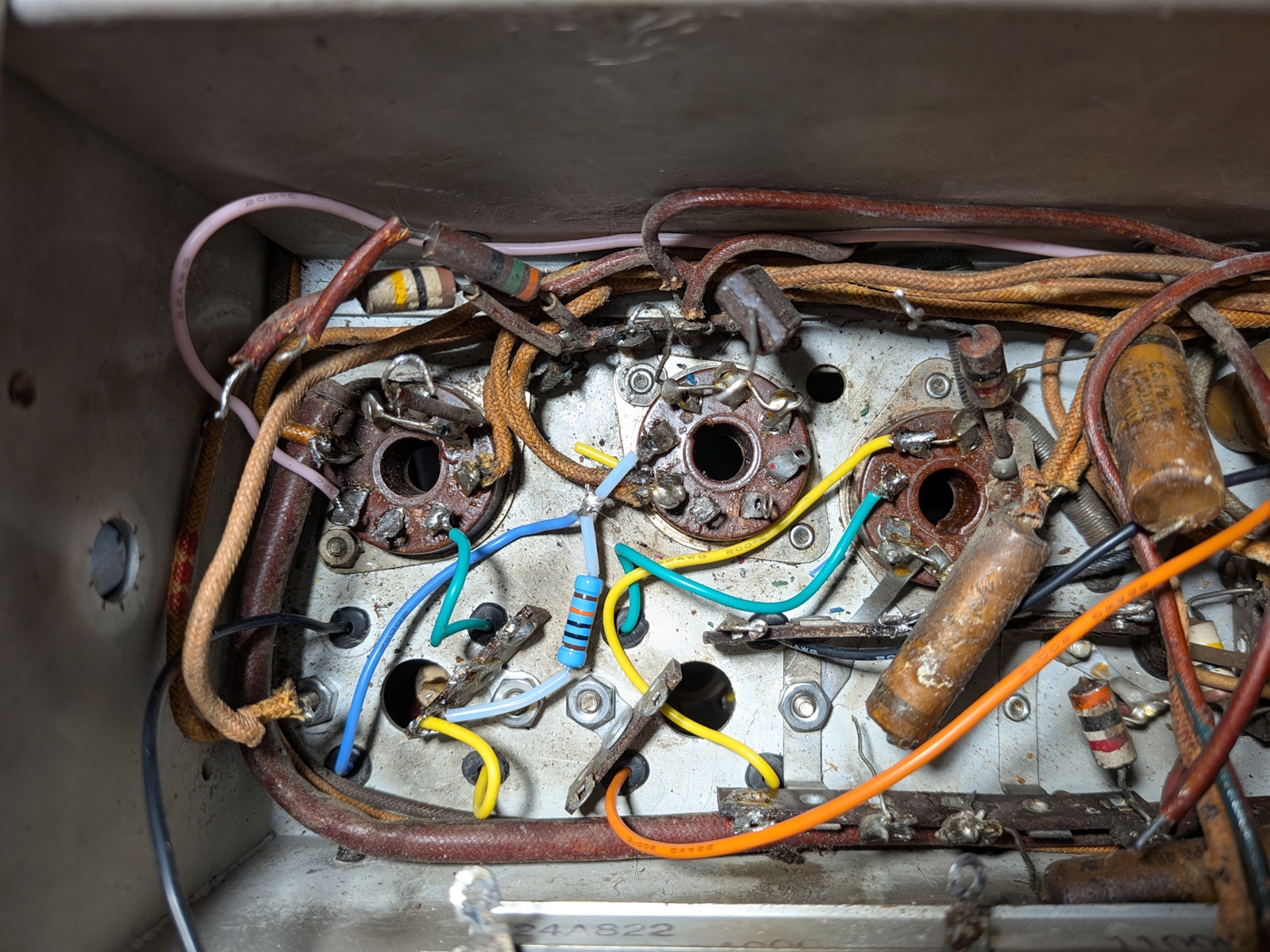
Second planning drawing. Only stupid so far is an attempt to put the 0.047 where the 470K goes.
Fortunatly, I realized it before it became painful to fix.
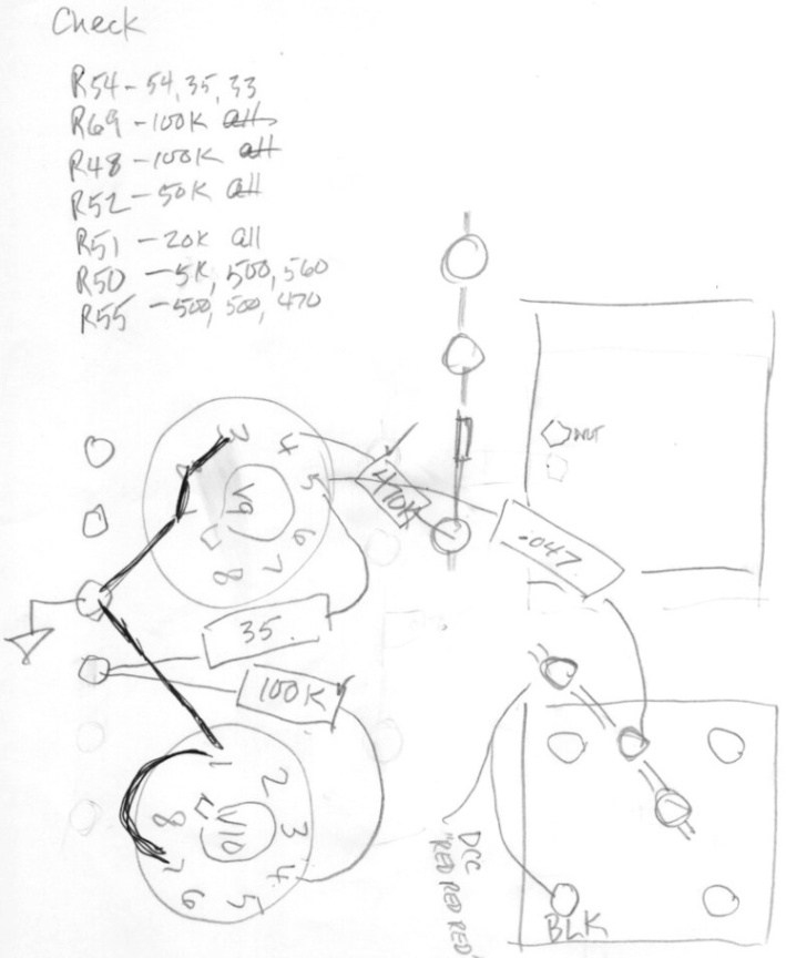
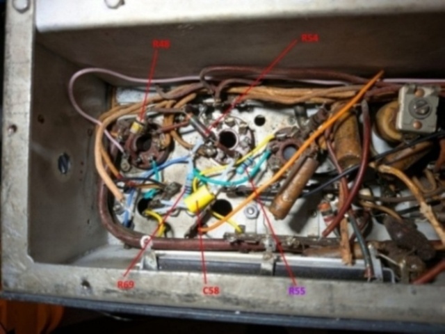
Step three.
Notes for rewiring:
Two green marks - Pot
Three red dots - single terminal under T5
Long green - wire from SW8-15
Black -
Footnotes:
Page: /5th_radio_resurrection/Recap_2/Recap_V9_V10.shtml
Last modified: Wednesday, 3 Jun 2026