Adjustment of the IF chain
With the crystal's exact resonant frequency determined and the phasing bridge
balanced, the next step is to align the entire Intermediate Frequency (IF) amplifier
chain to match this exact frequency.
Because we are aligning the IF strip independently, we must completely disable
the radio's Local Oscillator and RF front-end to ensure no stray signals
or mixing products interfere with our pure signal injection.
Required Equipment/Parts
-
470 Ω 10W resistor
-
A signal generator capable of producing a modulated sine wave. A digital one
is preferable as you will be asked to provide 455 KHz signals accurate to
a single cycle: 454,381 Hz for example
-
A scope with a 1X probe
Initial Radio Conditions
-
Power off. Radio right side up
-
Disconnect the speaker. Connect a dummy load resistor across the receiver's output
terminals on the rear of the chassis. A 500 Ω, 10 W resistor connected across
the 500 Ω output terminals is ideal
-
RF Gain to max
-
Volume to 50%
-
AVC off. To accurately view the peak of the signal, we must defeat the
Automatic Volume Control (AVC). If the AVC is left on, the radio will
automatically reduce the gain as you approach the perfect alignment
peak, making the peak look "flat" and broad, ruining your calibration
-
Selectivity Switch: XTAL SHARP
-
BFO off
-
To prevent the SX-28's native local oscillator from interfering
with the alignment: Remove V4 and place on the tube extender.
Set switch to 5. Connect test point to ground with a clip lead.
This cleanly kills the oscillation without altering
the DC current rails by removing the tube
-
Noise Limiter (ANL) off
-
Send/Receive to receive
Test Equipment Setup
-
Set your RF Signal Generator to the exact out-of-circuit series
resonant frequency of your crystal (453,621 Hz for my test radio). If your
stuff is antique, use a frequency counter to verify generator frequency.
This is important.
-
Turn on amplitude modulation on your generator. A setting of
30% or 50% modulation at 400 Hz (or 1 KHz) is
standard1
-
Set the initial output voltage to 200 mV p-p
-
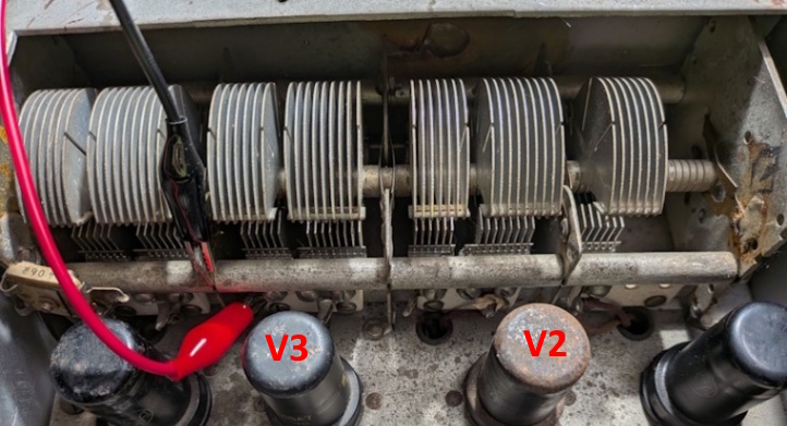
Connect the output of your signal generator to the signal grid of
the mixer tube (V3, 6SA7, pin 8). The easiest place to
do this is the third terminal from the front of the radio on
the main tuning capacitor (C2.1).
-
Scope is connected across the speaker terminals. Caution: The
probe ground needs to go to the grounded speaker terminal. It is
common2 that prior work on the radio has changed which
of the speaker terminals is connected to the chassis. Verify with an
ohmmeter
IF Strip Alignment
-
Power on. Allow enough time to reach thermal stability
-
Because AVC is OFF, a strong signal will overdrive the IF tubes
into saturation, causing the signal to flatten out (clip) at the
top and bottom. You cannot align a clipped signal. Keep your
signal generator output level as low as possible. As you
bring the transformers into alignment, the output will increase.
When it does, turn down the signal generator output down
Do not adjust the volume. In the end, the signal level will
be 1 mV p-p
-
Observe a sine wave at whatever frequency you set in the signal generator's
modulation on the output speaker terminals.
If you don't see anything:
-
Verify RF gain at max. If it's zero, you won't see anything
-
Connect a 10X scope probe to grid of the 1st IF tube (V5, 6L7,
top cap). If you don't see the modulated signal, increase the signal
generator output levels until you overdrive everything and see
something. As you adjust T1 below, decrement the signal generator
output to keep the measured signal as small as possible
-
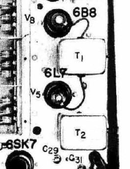
Adjust the aligning screws of T1. The lower screw is accessible
through hole in right mounting bracket. Adjust for maximum output on
the scope
-
Adjust the aligning screws of T2 for maximum amplitude
-
Adjust the air trimmer condensers at the top of T3 for maximum amplitude
Use a non-metalic screwdriver for this. Yes, they're caps but there is
enough voltage on the adjustment slots to zap you3.

-
Do not touch C29‐C31 despite what the Hallicrafters manual says
-
Because tuning one side of a transformer can slightly detune the other due to
magnetic coupling, repeat the sequence (T1, T2, T3) as many times as seems useful
to ensure absolute maximum throughput. Reduce signal generator output whenever
possible
Selectivity Symmetry Check
Now that the IF strip is perfectly peaked to the crystal's native frequency,
we need to verify the alignment holds together when the crystal is switched out
-
Increase your signal generator output slightly so you have a
strong, visible sine wave
-
Slowly step the front-panel Selectivity switch through its broader
positions (XTAL MED, XTAL BROAD, IF SHARP, IF BROAD)
-
The amplitude of the sine wave on your scope should increase as
the bandwidth widens, but it should not disappear or drop drastically.
If the signal remains strong across all positions, your IF strip is
perfectly aligned and unified
Footnotes:
-
It's also common that the audio output transformer has been replaced
with something that does not produce 500 Ω and 5,000 Ω outputs. If this
is the case with your radio, you'll need to adjust the speaker loading accordingly
-
So says Gemini AI. I don't think it makes a lot of difference. I was using
1 KHz at 80% and I was happy
-
I'll give you one good guess as to how I know this
Page: /Alignment/IF/Adjust/Align_early_if_adjust.shtml
Last modified: Saturday, 18 Jul 2026