What follows is word-for-word, including the HTML formatting that matches the style used on this website, from a Gemini response. See the source here.
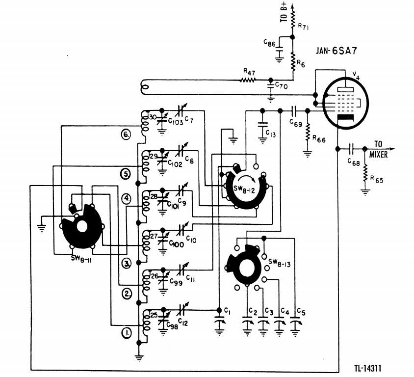
Before attempting to align the Local Oscillator frequencies, it is critical to understand the role of trimmers C7 through C12. These are the Oscillator Feedback Adjustments, and their job is to ensure the V4 (6SA7) oscillator tube provides a steady, uniform signal to the Mixer across the entire tuning range of each band.
A local oscillator is essentially an amplifier that feeds a portion of its output back into its input through a tuned L/C (inductor/capacitor) circuit. However, the efficiency of this resonant circuit is not constant. As you tune from the low-frequency end of a band to the high-frequency end, the ratio of inductance to capacitance changes.
Without compensation, an oscillator might barely have enough energy to sustain oscillation at the low end of the dial, while running so aggressively at the high end that the tube clips, distorts, and generates unwanted harmonics.
The V4 tube creates its own operating bias through a process called grid-leak action. On the positive half of the RF AC cycle, the grid draws current, charging a capacitor that bleeds off slowly through a resistor. This creates a negative DC voltage baseline (bias).
If you probe the oscillator grid with an oscilloscope, you will not just see a few volts—you will see a massive AC sine wave (often 100V to 200V peak-to-peak) riding on a deep negative DC baseline, sometimes as low as -50 to -70 VDC. The stronger the AC oscillation, the deeper (more negative) that DC bias becomes.
Trimmers C7 through C12 are variable capacitors placed in the feedback loop of the oscillator circuit—one dedicated to each of the six bands. By adjusting these trimmers, you control exactly how much RF energy is fed back into the grid of V4.
The goal of these trimmers is uniformity. By adjusting the feedback capacitance, we can smooth out the natural amplitude variations of the L/C circuit. We want the peak-to-peak AC amplitude (and therefore the resulting negative DC grid bias) to remain as flat and constant as possible as we sweep the main tuning dial from one end of the band to the other.
Why do we go to all this trouble before adjusting the frequency? The V3 Mixer tube relies on a specific "injection voltage" from the Local Oscillator to do its job.
By flattening the oscillator's output curve with C7 through C12 first, we ensure the Mixer operates at peak efficiency everywhere on the dial, giving the SX-28 its legendary sensitivity.
Page: /Alignment/Osc/Theory/Early_osc_feedback_theory.shtml
Last modified: Friday, 24 Jul 2026