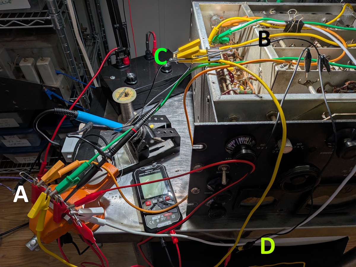
A = paperclip 'bus bar', B = clip to keep test leads from near‐by B+, C = R61, D = C66. Lead length is not an issue
If the AVC line is to be used as a calibration and alignment device, there needs to be a procedure to guarantee that it is working properly.
The first attempt at making this page was heavily influenced by the Gemini AI LLM.
There were a lot of errors, false starts and mistakes made.
You can read it here.
It is preserved because there's a lot to be learned from it, good and bad.
Unfortunatly, testing the AVC isn't one of them.
AVC Test
If the line drops to around -15 V with a strong signal and bleeds off
smoothly when the signal is removed, your AVC network is in perfect health.
It is fully certified to act as your alignment calibration device.
If the voltage barely moves (e.g., only drops to -2 V under heavy signal), V8
or V9 is weak, the AVC IF transformer (T6) is misaligned, or a resistor
in the voltage divider network has drifted high.
AVC Repair
The part of the page was heavily influenced by the Gemini AI
responses here,
here, here,
and here.
As noted above, a lot of it was wrong.
The repair process is pretty simple. Power off to start.
Unsolder all the wires (3) from the node plus a resistor (R61) and a capacitor (C66).
I found it useful2 to use a bunch of clip test leads and a paper clip as
a 'bus bar'. Run test leads from all the node components to the paper
clip and disconnect one at a time to isolate the source of trouble.
A = paperclip 'bus bar', B = clip to keep test leads from near‐by
B+, C = R61, D = C66. Lead length is not an issue
Need to develop procedures for voltage too high, low, not moving at all, etc.
Footnotes:
Page: /Avc_test_and_repair/Avc_test.shtml
Last modified: Wednesday, 29 Jul 2026