These band switch pages are probably correct but they have not been reviewed and verified. Test everything and if you see an error, please report. If you're happy with what you see here, please report that too. Thank you.
Some of the first documentation did not use '1st RF' and '2nd RF'. Those terms came into play later on. This website uses 1st and 2nd throughout.
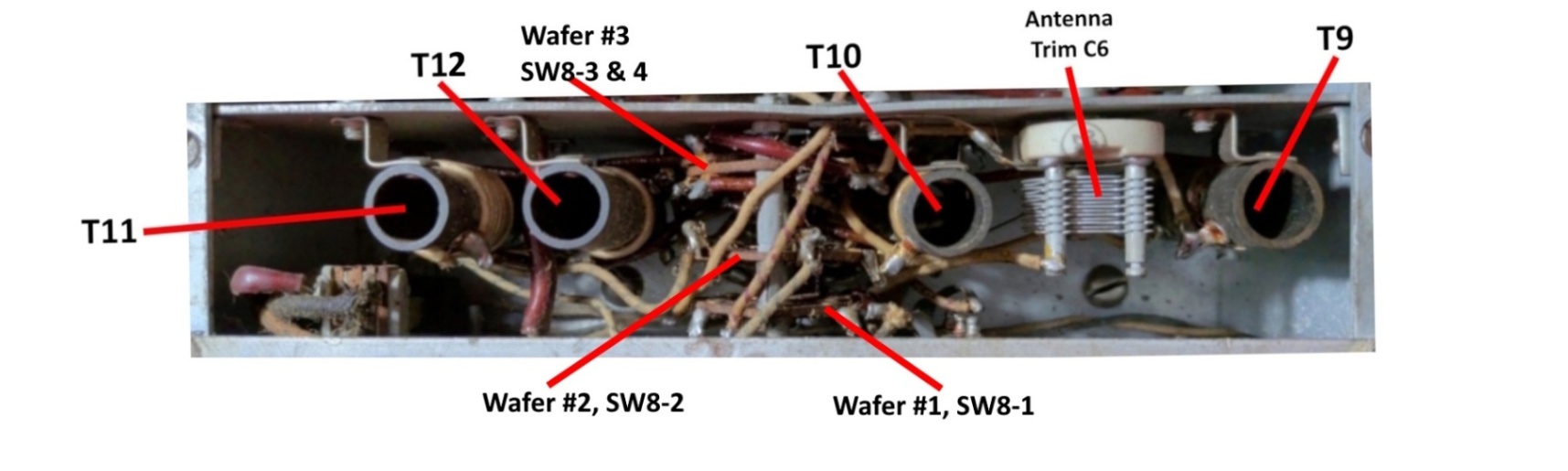
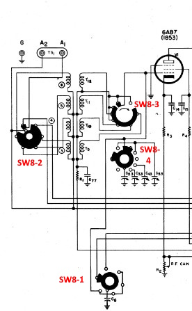
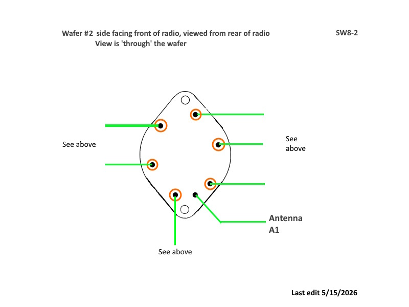
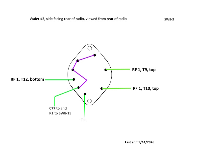
Wafers are counted 1, 2, 3... 10 starting at the rear of radio. SW8-1 ... SW8-15 are the schematic designators.
The early versions of the 1st RF module had two wafers: numbers #2 and #3 counting from the rear of the radio.
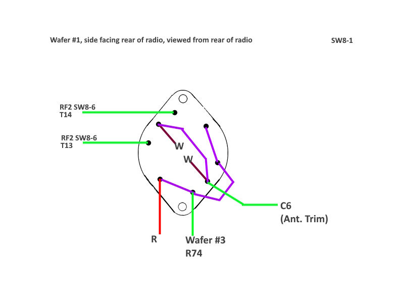
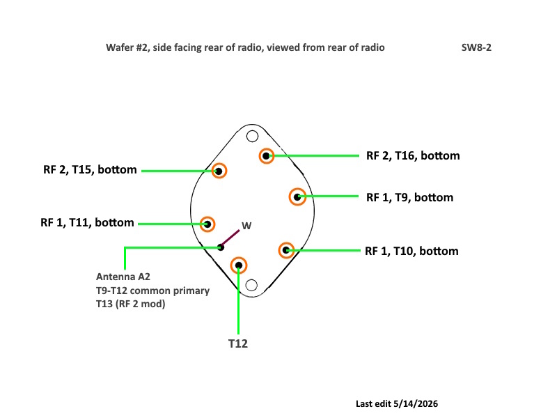
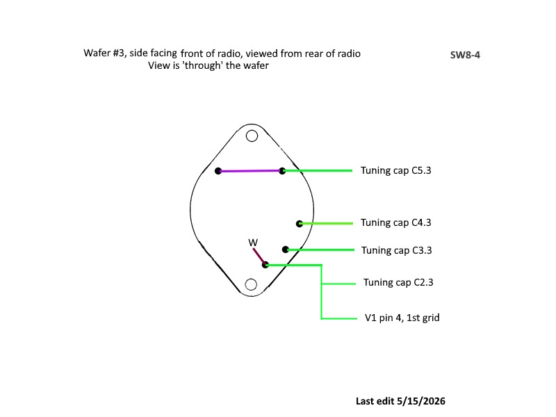
Purple wires are jumpers from one terminal to another.
Green is actual wire of any color or scheme.
Orange circles indicate connected terminals on both sides of the wafer.
Red is for components soldered directly to the wafer.
'W' means wiper.
Page: /Band_switch/Early/1st_RF_switch_wafers_B/1st_RF_switch_wafers_B.shtml
Last modified: Sunday, 31 May 2026