For all except one, there is an empty hole in the wafer next to the mounting screw. The holes next to the other screw are always filled.
The arrow points out the hole.

The whole point of this page is to provide some clues on figuring out which side of the wafer is what. Perhaps you have your own system.
With some exceptions noted below, it's believed this information applies to all SX-28 radios.
With the radio upside down and looking from the rear of the chassis...
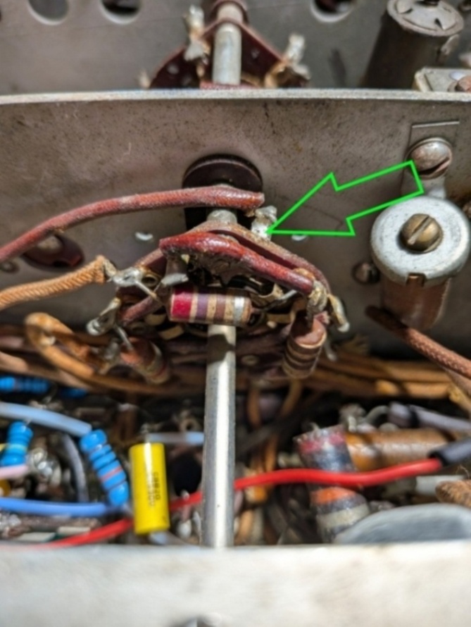
For all except one, there is an empty hole in the wafer next to the mounting screw. The holes next to the other screw are always filled.
The arrow points out the hole.
The oddball is the wafer on the outside of the oscillator module.
For one thing, it's mounted backwards. All of the switches, starting with the rear-most, are numbered 1, 2, 3, and so on.
Until you get to the last wafer and then the sequence is 13, 15, and 14.
Another thing is that some radios don't even have SW8-15. I believe there are some very early
radios (Summer 1940, FCC special order) that don't have this wafer at all.
The red arrow points to the hole due to a missing SW8-15. The green arrow points to
the hole filled with a contact for SW8-15.

This is from an SX-28A.

Page: /Band_switch/Wafer_orientation/W_o.shtml
Last modified: Monday, 1 Jun 2026