Note the modern fuse holder and the thermistor (10D-11, 3 amp, 10 ohm).

I made substantial changes to the original power supply design. The motivating factor was the fact that due to the 5Z3 design, the B+
was on the 5 VAC winding in an 80 year old transformer that uses paper and wax as an insulator. I considered that risky and avoided
the problem with a couple of $2 rectifier diodes. I also decided to use some modern parts since I'm going for function, not
authenticity. In this image, you can see the inrush limiting resistor, the modern banana jacks (Temu before it went nuts), and the
new fuse holder. I don't plan to install the external DC power
supply option.
I plan of leaving a 5Z3 tube installed for appearance's sake but no wires will be attached to it.
Stage 1:
Note the modern fuse holder and the thermistor (10D-11, 3 amp, 10 ohm).
For reference:

Stage 2:
Here I've added the diodes, filter caps, and dropping resistors.

Stage 3:
I installed a stubby power cord since I didn't want to be arguing with a long one for the next year or so as I moved
the chassis about. I stick an extension cord on it when I need it.

Rig up a dummy load and fire it up!

Stage 4:
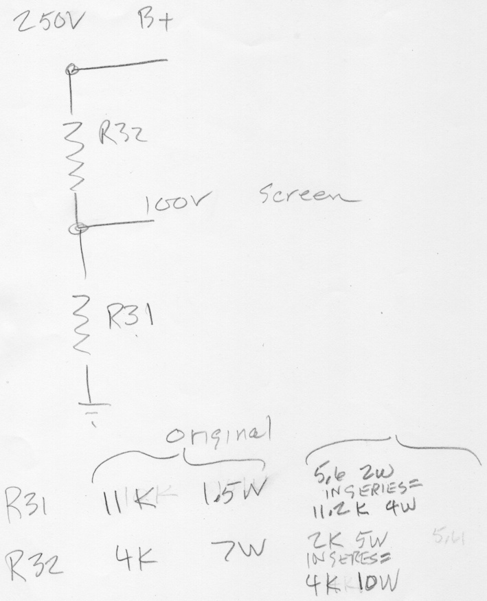
Here I've added the the screen voltage divider that I made using a combination of modern parts. The original dividers
were located on the opposite of the chassis and were quickly snapped up on eBay.

The power supply isn't regulated so the output voltage is determined by the input line voltage and the load. Pretty risky.
I would like to add some zener diodes to limit the B+ voltage to around 300 volts. I have some 1N5383BRLG which do 150 volts.
I figure 2 of those in series with a 10 ohm resistor in parallel with a similar string ought to get the job done.
Page: /Power_supply/Power_supply.shtml
Last modified: Friday, 24 Apr 2026