Schematics
Showing the schematic in a web page is not particularly useful. It's huge and you can't read scaled down versions.
It's important to note that there are many different versions of the
schematic and I've not met one yet that accurately reflects the radio I'm looking at, whichever one it is.
There are three different methods of showing switches and all of them are terrible.
The file type is JPG. If you think something else should be provided, send email.
If you have a different version and would like to share, would love to add it here.
Early SX-28 Radios
-
This version:
-
Does not have SW8-1, SW8-14 or SW8-15.
-
Shows V1 (6SK7) pin 3 connected to ground.
-
Has four 6SK7 tubes and no 6AB7 tubes.
-
Has the single ended audio output: only one 6V6.
-
Schematic recreated from one dated 20 July 1940.
Download the recreated here. Download the original here.
-
This version:
-
Does not have SW8-1, SW8-15. Does have SW8-14.
-
Has two 6AB7 (1853) tubes and two 6SK7 tubes.
-
Shows V1 (6AB7) pin 3 connected to ground.
-
Schematic dated 18 December 1940. Found in a document dated 1941.
Download the recreated here. Download the original here.
-
This version:
-
Has all of the SW8 switches (1-15).
-
It still shows V1 pin 3 connected to ground.
-
Shows all of the fixed caps on the RF transformers.
-
Ttitled Fig 13-SX28-SCHEMATIC.
-
Schematic dated 8 April 1942. Found in a Navy manual marked 16 December 1942.
Download here.
-
There is (should be) a version of the schematic for the radio just prior to the switchover to the 28A showing
V1 pin 3 connected to V1 pin 5. I believe my radio #4 was one of these but no way to tell now.
Late SX-28A Radios
-
This version titled SX-28-A-SCHEMATIC. Shows C83 on T23.
Download here.
-
This version titled AN/GRR-2. Has some component values. Shows C83 on T23 and C114 on T20.
Download here.
-
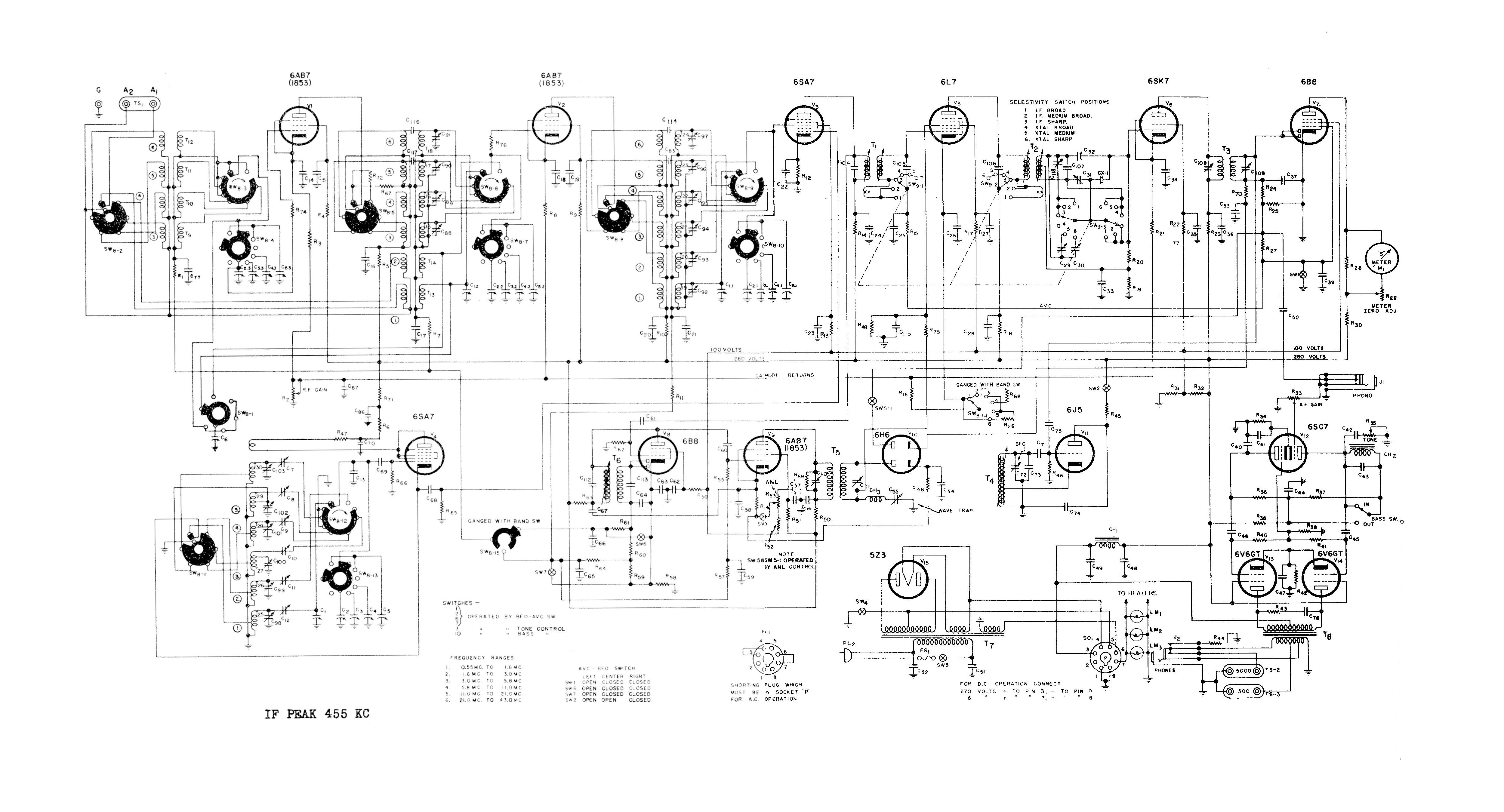
This version from Ryder volume 16. No component values. Shows C116 on T18 and C117 on T17.
Shows V1, V2 and V9 being 6AB7 (1853).
Download here.
"Simplified Schematics" for Late SX-28A Radios
Simplified schematics are from Ryder's volume 16 and show only the parts in play for a specific band. Very useful.
-
Band 1. Download here.
-
Band 2. Download here.
-
Band 3. Download here.
-
Band 4. Download here.
-
Band 5. Download here.
-
Band 6. Download here.
The version for my now-abandoned SX-28A build
-
It's not original. It uses rectifier diodes in place of the original tube.
The red line is B+. The blue line is the screen voltage.
It has the colors I used to rewire the transformers.
If you're going down the modified route, this might be useful as a basis for your own schematic.
Download here.
Page: /Schematics/Schematics.shtml
Last modified: Saturday, 30 May 2026