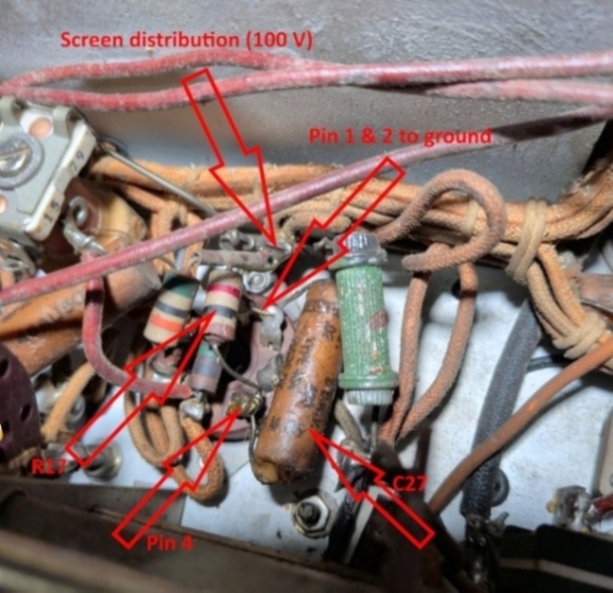
Clipped it on one end and measured: 200ish ohms! Don't recall ever seeing a capacitor turn into a resistor. Must be Gremlins. After cap replacement:
TUBE/PIN EXPECTED R TO GND GUESS R TO SCREEN V V5 pin 4 12,000 10,780 1,000 ??
With a test lead connecting the center tap of the screen resistor to a sort of burnt looking wire that obviously used to be connected, measured screen voltage of around 40 volts.
Disconnected the test lead and measured no load voltage on the screen divider tap of around 200 volts (should be 100 under load). The DC resistance to ground on the burnt looking wire that used to be connected to the tap was about 870 ohms.
Something is drawing down the voltage so resistance checking is in order.
Prior to doing anything else, I decided to re-do the entire 15 tube resistance-to-ground testing since my breakout box had
a short and the output transformer was missing the last time I did it.
Made sure the radio is configured like this.
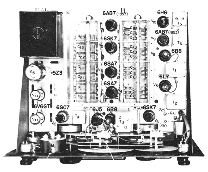
Tube location picture.
			TUBE/PIN    EXPECTED    R TO GND    GUESS    R TO SCREEN     V
			V7 pin 6     10,000       974        0          .2

			V6 pin 6     12,000      2,110     1,000       1,140

			V5 pin 4     12,000       166      1,000        810

			V3 pin 4     400,000     2,150

			V2 pin 6     12,000      2,140
			TUBE/PIN    EXPECTED    R TO GND    GUESS    R TO SCREEN     V

			V5 pin 4     12,000      10,780     1,000       ??
Page: /5th_radio_resurrection/Screen_voltage/Screen_voltage.shtml
Last modified: Thursday, 23 Apr 2026