
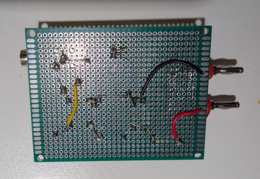
The original version of this page was justifiably criticized as being too complicated. You can read it here. It contains all of the reasoning for what comes below.
In order to connect the signal generator to the antenna inputs, a matching circuit is needed.
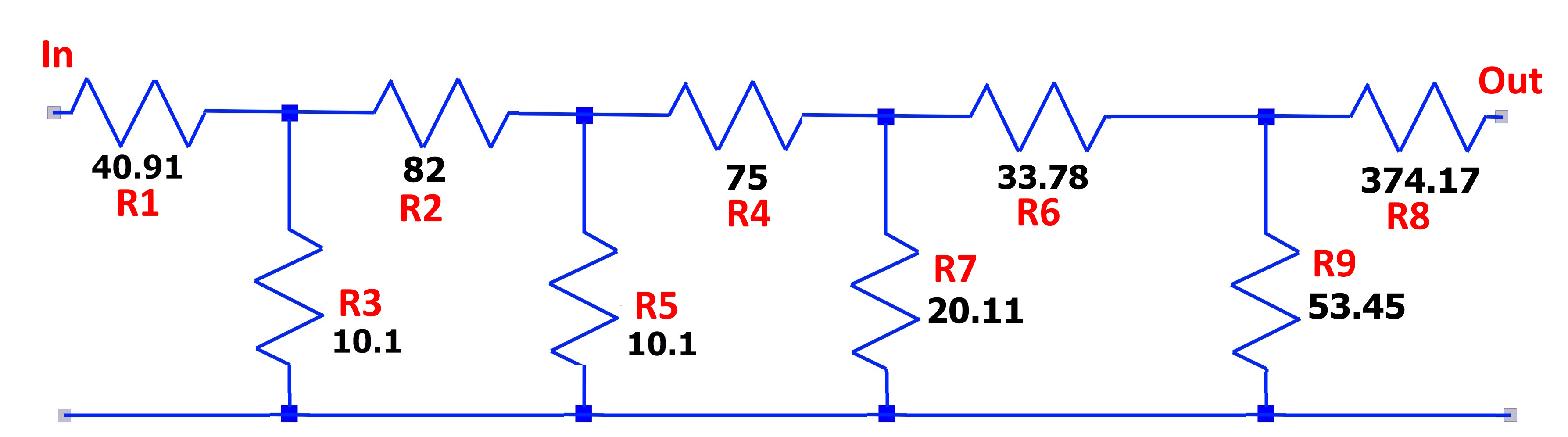
For R1, parallel two 82 1W resistors to make 41 Ω.
For R2, a single 82 Ω 1W resistor.
For R3 and R5, cherry-pick pick 10.1 Ω from the 10 Ω bin.
For R4, 75 Ω.
For R6, cherry-pick a 33 Ω from the 33 Ω stock.
For R7, parallel 43, 43 & 330 to make 20.18 Ω.
For R8, in parallel 750 & 750 to make 375 Ω.
For R9, parallel 120, 120 & 470 to make 53.2 Ω.
Set signal generator to 10 V p-p, 50 Ω. Connect to input.
Connect scope (or whatever) to output. Measure 10 mV p-p.
Page: /Antenna_matching/Antenna_matching.shtml
Last modified: Thursday, 23 Jul 2026