Mickey, Zephyrhills, FL, late June 2026...
I generally prefer short and sweet "this is how you do that" but as you shall soon see, that's not going to be the case here.
In order to connect the signal generator to the antenna inputs, a matching circuit is needed.
Google's Gemini (AI) was asked2 to provide a suitable circuit. The initial result
was encouraging but had some elements that were not clear to me. Subsequent inquiries provided
different answers, sometimes from identical prompts.
AI is not straight forward. This whole exercise turned into as much a lesson about AI as it
did matching circuits. See 1, 2,
3, 6, and
7, for the whole story.
The circuit below is from the #7 conversation. The other responses placed the 50 Ω to 400 Ω conversion first and incorrectly stated that the voltage would rise as a result. I guess it assumed inductors were being used. #7 did it the other way around.
The circuit consists of four cascaded stages. The circuits are composed of carbon film resistors only. This removes any frequency considerations from the calculations, at least for the relatively low frequencies used here. There are always parasitic inductance and capacitances but by keeping lead lengths very short, they are thought to be minimal.
Gemini did not produce a schematic for this solution but it is simple enough to make one. I used LTspice (barf) and Paint.net to make the images below.
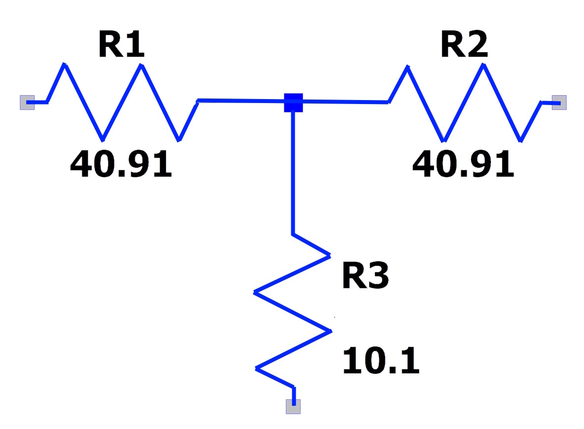
Two 20 dB attenuator (50-ohm T-Pad) in series.
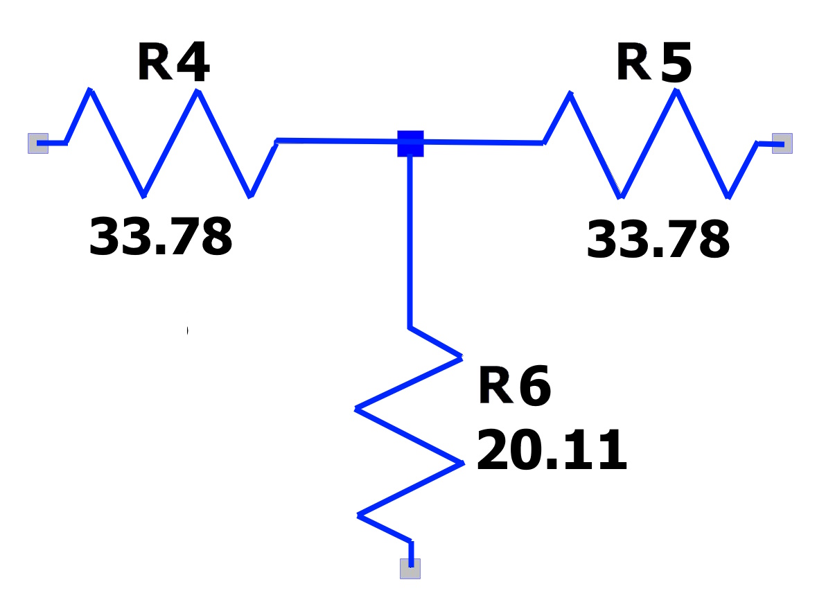
A 14.27 dB attenuator (50-ohm T-Pad)
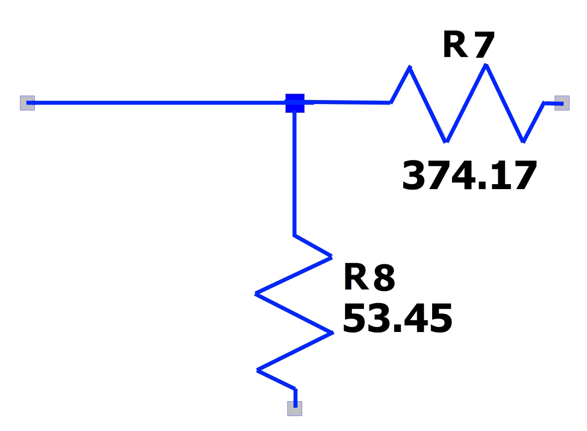
A minimum loss matching pad (50-ohm to 400-ohm L-Pad)
Since stages 1 and 2 in series have two 40.91 Ω resistors in series, a single 82 Ω resistor will work. I'll call that R2-1.
Likewise, stages 2 and 3 in series have a 40.91 Ω resistor in series with a 33.78 Ω resistor.
A single 75 Ω resistor will work. I'll call that R2-3.
Since this is intended to be part of a calibration or alignment procedure, getting as close to the calculated values
is best. The only concern wattage-wise is in the 1st stage.
There's nothing magic about these values. Any combination of standard values combined
to make the required value will work. The values shown here are what I had on-hand. There are many parallel
resistance calculators on-line to help with this.
If selecting your own, keep in mind that using different values in parallel (or series) rather than multiples
of the same value from the same lot is best. For example, if you need 11 ohms, don't parallel three
33 ohm resistors from your stock. They most likely came off the same production line and all have the same tolerance
error. Use, for example, a 33, a 25 and a 47 (makes 10.92). The tolerance errors are as likely to offset each other as anything else.
If you're inclined to condense all these resistors into just a few, read the the 7 page. More is better.
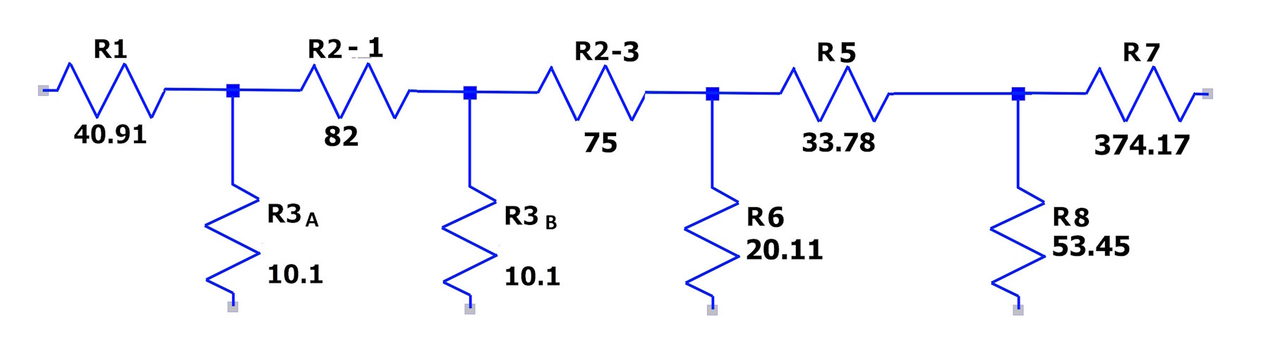
For R1, parallel two 82 1W resistors to make 41 Ω.
For R2-1, a single 82 Ω 1W resistor.
For R3, cherry-pick a 10.1 Ω from the 10 Ω stock.
For R2-3, 75 Ω.
For R5, cherry pick the best from the 33 Ω stock.
For R6, parallel 43, 43 & 330 to make 20.18 Ω.
For R7, in parallel 750 & 750 to make 375 Ω.
For R8, parallel 120, 120 & 470 to make 53.2 Ω.
The result. I had already picked out the circuit board so it's bigger than needed. Most of the resistors are much higher wattage than required. The '5 minute epoxy' I used on a warm day is worthless. It was still sticky after 18 hours and it ran all over everywhere. I need to toss that brand and buy good.

Footnotes:
Page: /Antenna_matching/Antenna_matching_original.shtml
Last modified: Saturday, 4 Jul 2026