
V1 is in the first RF module. It is a 6AB7 or a 1853 type.
When making pin-to-ground resistance measurements, make SURE the radio is configured like this. To locate tubes, see this.
There are two different wiring diagrams for V1. An early one shows pin 3 to ground, a later one shows pin 3 to the cathode on pin 5. It's assumed that with pin 3 going to ground, it's 'a very early' radio and with pin 3 connected to pin 5, it's 'a later early' radio or a late (SAX-28A) radio.
Resistance measurements made with Simpson 260.
"Open" or "no pin" means the tube does not use the pin but it might have been used as a junction for other components.
		Pin to         Radio       Radio     Radio
		chassis         #5          #6        #7

		1               0           0          0

		2               0           0          0

		3               0           0          0

		4            668,000       0.39    1,400,000

		5              334        9,200       300

		6            30,170      76,000     39,000

		7              0.2         .2         .2

		8             1,169      50,000      1,500

Resistance measurements made with Simpson 260.
"Open" or "no pin" means the tube does not use the pin but it might have been used as a junction for other components.
		Pin to         Radio
		chassis         #_

		1               0

		2               0

		3              334

		4            668,000

		5              334

		6            30,170

		7              0.2

		8             1,169
		Pin to       From the
		chassis        docs

		1               0

		2               0

		3              350

		4            900,000

		5              350

		6            44,000

		7              0.1

		8            15,000
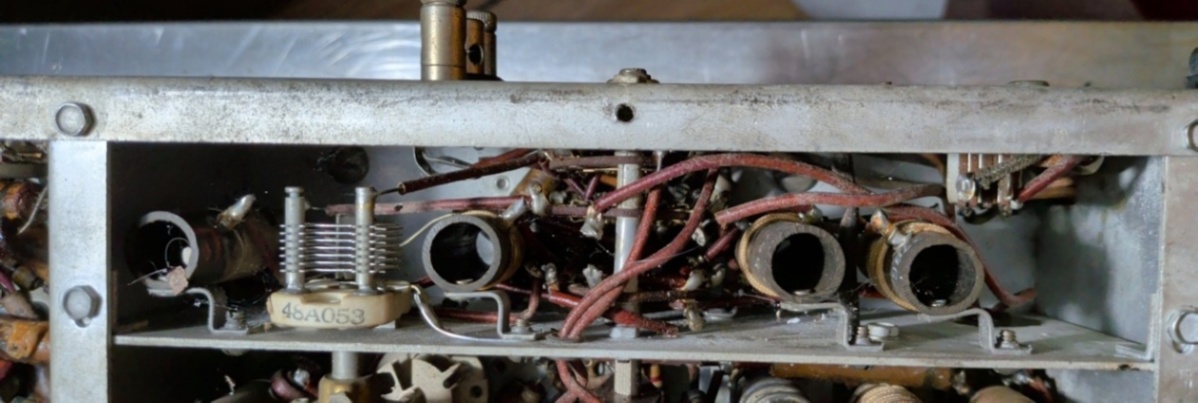
The old schematic shows variable caps on the secondary of the four transformers in the 1st RF module. The '5th' radio does not have them.
Tube pinout images are found on tdsl.duncanamps.com
For reference:


Page: /V1/V1_new.shtml
Last modified: Monday, 1 Jun 2026