I Need Help #2

I was having trouble making sense of something so I started another 'I need help' page.

It started out about my attempt to match my far-from-optimum antenna to my #7 radio which works but not very well. I learned that if excellent sensitivety for an SX-28 is 2‐4 µV, my radio is about 35 µV. And that's just a guess.

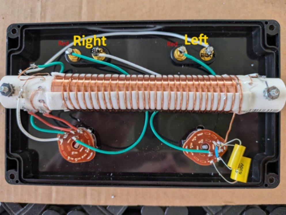
Having some stuff laying around and wanting to keep my hands busy while sitting on the porch shooting the breeze with my lovely wife, I made this:


I didn't have any plans to follow and I don't know a whole lot about this sort of thing so I was going with something like "The box is 7½ inches wide inside so let's start with 7 inches of ½ inch PVC."

"Let's wrap a bunch of enameled 26 AWG around it and put a bunch of taps on one end since we have no clue what the antenna impediance is and we think the radio is 400 Ω"

"Let's put some sticky tape on it and make another winding using 18 AWG and space the turns out a bit."

I am not joking.
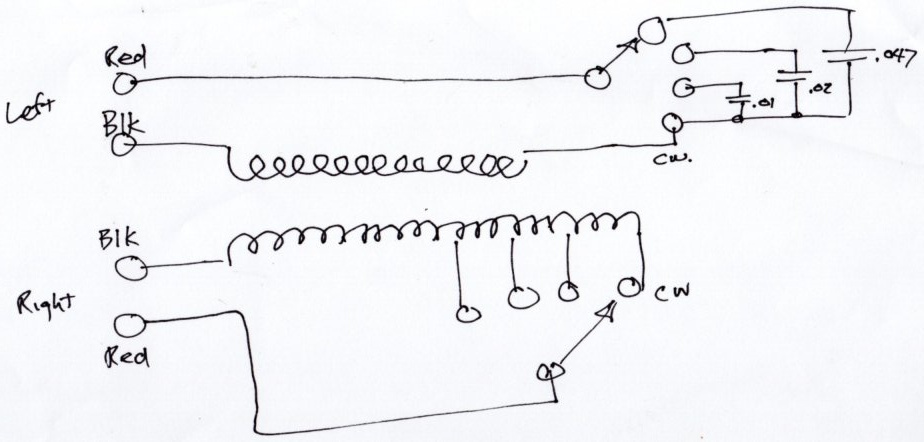
I have two leads coming in from the outside:

I have two leads to the radio:

Here's where it got weird. When I connected the box up one way - red to red, black to black, etc - it worked OK and I could pick up some stations. When I reversed one of the windings, it didn't work at all. I didn't understand this. Turns out there's a lot I didn't understand.

I decided to ask Google's Gemini AI Large Language Model (LLM) and embarked on a wide ranging conversation that started with the box above (apparently I'm a genius or Gemini is a schmoozer) and wound up touching on all sorts of other topics.

The conversation is very long and is getting longer.

I've sliced the conversation into pieces in the form I've used elsewhere on this website. They are not discrete questions - one depends on what has transpired before. The items below are the prompts with links to the responses. The 'first', 'second', 'third' bit records the order in which I asked the questions. That's important.

Since the conversation wanders all over the map, I wanted to come up with a scheme that sorted the mess out. Seperate pages were considered and rejected. I opted for background colors to indicate what was going on. Pink means it's a bad answer or the prompt is addressing a bad answer1. You can pretty much skip over these. There might be some good bits in them which will be pointed out in italic comments. Yellow means its about the subject that got us here - the box.

1st prompt: In an antenna balun, why does reversing one winding destroy the signal

Opposing currents in the windings are discussed. Why switching one destroys operation.

2nd prompt: What happens if a toroidal core is replaced with two air core coils with one wound on top of the other?

Describes why air is less efficient than a toroid.

3rd Prompt: I am attempting to connect a poor quality long wire antenna to a Hallicrafters SX-28 receiver. The air core overlapping coil balun I built works but I don't understand why. The coil has approximately 30 turns on the antenna side and approximately 150 turns on the receiver side

Describes why the box works. "You accidentally engineered a classic 1940s ‐ style antenna coupler using period ‐ accurate physics"

4th prompt: The antenna input consists of 2 wires: one from a metal roof and another from a long wire suspended 18 inches above the metal roof. The long wire is near the edge of the roof and some 6 feet below the peak. The total length is about 35 feet

"Ah, this changes the picture completely!" More on why the box works only using different reasoning.

5th prompt: The antenna trimmer does not seem to affect anything. The receiver is not very sensitive. I need to provide about 35 microvolts of modulated sine wave from a signal generator to hear the modulation through the speaker. The local oscillator is aligned with consideration of the 462 khz crystal (should be 455 khz) and the if chain is aligned to the 462 khz crystal

The start of the discussion of why the radio does so poorly. The mention of the 462 KHz crystal is root of the issues. As it turns out later, it's not really 462 KHz and since the radio is aligned to that bogus number, everything is pooched.

6th prompt: I read somewhere that the crystal used in the SX-28 is very specific to the design and can not be replaced with anything modern. Is this true? Can I use a modern crystal at exactly 455 khz?

7th prompt: I have an OWON DGE1060 with an attenuator circuit to drop the minimum 1 millivolt output to 1 microvolt. The attenuator circuit was provided by a different conversation with Gemini

8th prompt: I have been working with band 1 (AM) which doesn't even use the first RF stage on the theory that the lower frequencies would be less affected by stray wires and noises

9th prompt: There are mistakes in your previous reply. The capacitor numbers (C6, C1 and others) are all wrong. You mention 'on top of the gearbox gear tower' which makes no sense. You mention 'the top-side trimmer capacitors' yet there are no topside trimmer capacitors unless you are referring to C29, 30 and 31

10th prompt: Another error: there no adjustments on the 'sides of those individual band compartments'

11th prompt: More corrections: there are no cast or aluminum chassis parts. Everything is heavy gauge galvanized steel. As you noted before, the Antenna Trimmer (C6) is located in the 1st RF compartment (closest to the rear of the radio) but is not used on bands 1 and 2. The frontmost compartment is the local oscillator

12th prompt: The procedure I used to align the oscillator at 600 KHz was to adjust the tuning slug in T25. If it was not possible to find a peak (the 462 KHz crystal is at the limit of specified tolerance and makes this difficult), I adjusted C12 which seems to vary the amount of feedback to the 6SA7 first grid rather than be part of the L-C tank. C12 is marked as 'factory set, don't adjust' in the Hallicrafters alignment procedure. This worked for band 1 but did not for some of the higher bands.

13th prompt: I'm sure that when Hallicrafters manufactured the radio, they adjusted C12 before saying 'do not adjust this'. What procedure did they use to adjust C12 (and the other feedback capacitors C7-C11)?

14th prompt: R11 is 100k ohms and appears to be part of the BFO. Did you mean R66 which the parts lists say is 50K?

15th prompt: I am writing an alignment procedure for the entire SX-28 radio for my website (https://sx28.info) and it is my goal to have a procedure for every adjustable thing in the radio instead of relying on something someone did 80 years ago and said 'There, it's done. Don't mess with it'.

16th prompt: I plan to include anything I can. I considered asking the names of the 12 engineers who designed the SX-28...

17th prompt: I already have a few words on the oscillator theory at https://sx28.info/Alignment/Osc/Theory/Align_early_osc_theory.shtml but anything you could add would be very helpful

18th prompt: I need to make major corrections to the '150-turn' coil. First, its 302 turns of 22 AWG wire wrapped around a length of one half inch PVC water pipe. There are taps at 197, 237, and 270 turns. It is wound counterclockwise per your question. The winding is single layer with no space between turns. Dimensions of the '30-turn' coil to follow

First of these three used the wrong wire guage.

19th prompt: I need to correct a typo - the wire gauge is 26, not 22

Fot reasons unknown, Gemini was using a length of 5 inches instead of 4.5

20th prompt: The total length of the 302 turn coil is 4.5 inches

This is the corrected response that started out with "That is a massive correction, and it changes the entire physics of what you have built!"

21st prompt: 67 turns per inch exactly matches my calculation. To wind the other coil, I put 3 pieces of double sided compressible foam tape along the outside of the 302 turn coil to hold the next coil in position since it is not closely spaced. There are 28 turns, also counterclockwise2, evenly spaced over the 302 turn coil. I connect the antenna to the 28 turn coil and the radio to the 302 turn coil. Selecting which tap to use does influence the quality of reception on the AM band.

"That changes the entire behavior of the transformer! Since both the 302-turn secondary and the 28-turn primary are wound counterclockwise, you have built an in-phase (additive) transformer"

22nd prompt: There are some significant errors here. The OWON signal generator is not in play at all. The input to the balun is the long wire and the metal roof. This is connected to the 28-turn coil and the (optional) capacitors. The output (the 302-turn coil) goes to the antenna A1 and A2 terminals. A2 is not connected to chassis. None of this is connected to earth ground either via the ground terminal on the power line into the radio (3-wire plug with 2 amp fuse) or anything outside (copper ground rod for instance). BTW - modern houses have plastic water pipes so grounding to a water pipe is pointless

23rd prompt: If the existing capacitors are useless, is there anything that could be done to improve the situation. Modifying the coil itself is a problem. Replacing the capacitors with say a 500 KHz high pass filter is not a problem. Or anything else for that matter. I have quite a selection of small inductors in the microhenry and millihenry range.

24th prompt: As an experiment, I tuned the radio to a strong local station (970 KHZ WFLA) and reversed the connections to the balun. The antenna goes to the 302-turn winding and the 28-turn winding goes to the radio antenna inputs. There is no significant difference in the sound of the strong station. Reversing one of the windings also has no significant effect. With the winding still reversed, only one or two other stations are detected, none of them clear. Restoring the backwards winding, with the primary/secondary reversed, and the number of stations seems to be better than any previous configuration

25th prompt: With the primary secondary reversed, 970 KHz seemed to fade a bit and 760 KHz came blasting in. I switched things back to the original configuration and now both are strong. I did a more careful scan of the entire AM band and found 15-20 stations with several strong enough to cause some minute movement of the S meter. It seems the 28-turn primary and 302-turn secondary works best. Not good but better than the alternatives.

26th prompt: Going back to the crystal, I have another SX-28 crystal out of the circuit that may resonant at 453 KHz. I tested it with a signal generator and a scope but I am not sure the best method of testing the resonant frequency either in or out of the circuit.

27th prompt: Using your setup, I measure about 12 mV p-p on the scope at 452.983 KHz. Modulation is off.

28th prompt: Two points: one: the crystal is still attached to the two-lug terminal strip so I'm just going replace the entire thing and two: doesn't the local oscillator need to be de-tuned from it's present 462 KHz offset and re-tuned to the 453 KHz offset?

From what I gather, once the crystal is sorted out (properly measured, circuit adjusted), the IF strip adjustment takes precidence over everything else.

29th prompt: The local oscillator tube is a 6SA7 (V4)

30th prompt: All of my schematics show a 6SA7 as the local oscillator tube. In a previous reply 'frequency pulling', you used 6SA7. The only 6J5 I see is the BFO oscillator (V11)

31st prompt: The military manual from December 1944 shows 6SA7 as the local oscillator. I have never seen any other tube in that position

32nd prompt: With the old crystal out of the circuit and in the same test jig as before, the frequency peak is 453.621 KHz and the amplitude on the scope is 13 millivolts p-p. Is there a reason why I measured 462 KHz in-circuit?

33rd prompt: More errors: C40 is a 500 mmfd fixed cap in the audio pre-amp section and the crystal does not go anywhere near T1. It sits between T2 and V6. It appears that C32 (5-50 mmfd) is the phasing control. Adjustable capacitors C29-C31 are also in the circuit.

34th prompt:


Footnotes:

  1. Correcting the model is a good thing. Hopefully it won't make the same mistake for someone else and the incorrected information may improve a subsequent answer.
  2. My initial prompt used the word 'clockwise' instead of 'counterclockwise'. The answer was all wrong so I corrected my mistake and got the proper answer given here.


Page: /1_need_help/Need_help.shtml

Last modified: Tuesday, 14 Jul 2026