As noted elsewhere, I identify the radios I have by the order in which I acquired them.
This page is about trying to make the 5th one actually run again. The 5th radio is the
oldest of all the radios.
I say 'blog' because it turned out to be a list of what I did, not what you're supposed
to do. If you're bored, you might find it interesting.
See here for info on the original radios.
Except for a few knobs and it's complement of tubes, the 5th radio was pretty much complete. The power supply
section had seen some rather rough maintenance and the cap on the RF Gain Control was hanging out by one wire.
The following pages address the issues in more or less the order I took.
Filter Caps - Remove the cans, add terminal strips, install modern mylar electrolytics.
R2 - Redo the RF Gain pot.
I started to do some resistance testing to update the V15 tube page and discovered I had carried a lot of wiring errors over from whoever butchered this thing last. I discovered that the filter choke is the wrong part but that really isn't an issue because it's open.
Power Supply - Rewire the AC input.
Got to the point where I could do the resistance to ground check for every tube. Since the power supply
filter choke is still missing, some tubes will have to be re-tested.
I found an anomaly while testing V1. The SX-28A documents and schematics show pin 3 connected to pin 5.
An early schematic for the SX-28 shows it going to ground.
I documented it on the V1 page.
Got the new choke. As it is larger then original, had to drill more holes.
Plug it in, turn on the power, nothing.
Check fuse, looks OK.
Gave up for the day.
First thing next morning, lights on panel, 5 VAC on 5Z3 filament, tube is hot, measure about 180 B+. Fuse mus not have been seated
properly.
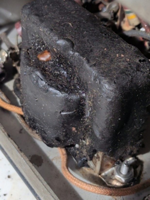
Next thing I know, I've let the smoke out of the output transformer. As ugly as this thing is, it won't bother me a bit to
replace it. The only problem is finding one suitable.
Existing holes are 2.8125 (2 13/16")
        Possible replacement parts:

        Hammond 1750E   8,000 primary   8 ohm secondary   2.813 mounting

        Hammond 125J    4,000 primary    NO
 With the output transformer removed, I powered on and measured B+ at 580 volts! I can see it's hooked up to the two resistors
feeding the osc and mixer modules but apparently nothing else. I attached my dummy load board which brought the voltage down to 380ish
With the output transformer removed, I powered on and measured B+ at 580 volts! I can see it's hooked up to the two resistors
feeding the osc and mixer modules but apparently nothing else. I attached my dummy load board which brought the voltage down to 380ish
Received the new transformer from Hammond:

Using my spiffy 'new' Simpson 260, the primary measures 315 ohms. Using my 4-wire ohmmeter, the secondary measures 0.45 ohms.
While measuring, decided to measure the incorrect part number output transformer found in one of the radios.
The primary (end-to-end) is about 585 and the secondary is 0.51 ohms.
Measured the damaged transformer also found in one of the radios, one half of the primary measured 260 ohms. The other half is open.
One would assume end-to-end would be 520 ohms. Didn't bother with the 4 secondaries. (One winding, 3 taps)
B+ looked OK. Went up to 350 then back down to 300ish as things warmed up.
Did the tube temp test. Nothing amiss.
Noticed the screen voltage was about 45 volts. Should be 100ish.
Started debug.
B+ now measures 300 and screen is 138 volts. Good enough for now.
Noticed S meter adjustment pot on rear of radio is very erratic. Got it to be more or less good and ignored for now.
Since my little scope module (uses PC screen) would melt if it came in contact with anything north of 35 volts, I ordered an old school Tektronix 465B from eBay. First introduced in 1972, this one was made in 1980.
It finally arrived. Checked it out with the on-board calibration signal generator...
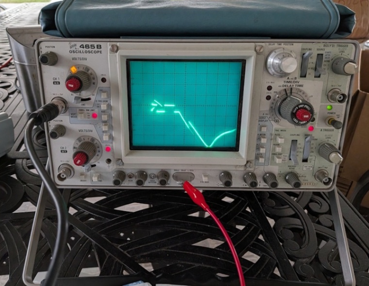
Now I'm in the scope repair business.
I got some of my money refunded and am now waiting for another scope of the same model.
In the interium, I hooked my PC's audio output up to the radio's phone input and listened
to Ahab the Arab on an 80 something year old SX-28. Cool.
Second scope arrived, it works, started doing the stuff I've outlined at the top of the CPR page.
Did not fix anything. I did show that signals coming in the antenna terminals are making it to the speakers
but without any modulation information. In other words, it can detect radio stations, it just can't
figure out what's being transmitted.
Decided to cycle through the tube box. During this test, I had the antenna hooked up and the
signal generator, still producing 1,400 kilocycles, clipped to the antenna wire insulation. (The only 'connection'
being the capacitive coupling through the insulation.) Output voltage at 250 millivolts.
It produces a carrier signal similar to the stuff I'm getting from the antenna.
V10: Carriers seemed louder so put the original in my 'marginal' bag.
V6: No significant change
V7: #1: Volume significantly reduced. #2: Better but maybe slightly less than the one I took out. Original back in, same as expected.
V9: No effect. None expected really.
V5: No effect.
V10 again: No effect.
V12: As expected, no effect on problem. Volume seems reduced. Replaced original and put the 2nd one in my 'marginal' bag.
V8: Slightly increased carrier sounds.
Was going to try V11 (BFO) but I turned on BFO and it worked as expected on the carriers. Not messing with it.
Noticed that the selectivity switch had a dramatic effect on the operation and I remembered that the knob is probably not
correctly installed. Given the state of the capacitors, an examination is called for. Also noted there are almost no underside pictures
of the 5th radio in the Original Radios section.
Started selectivity switch debug. Wasn't long before things improved.
Now I need a proper antenna. I threw a spool of wire out the window and put up maybe 20 feet clipped to the siding on the back of the house. No significant improvement.
I need to replace the S meter pot on the back of the chassis.
Most of all, I need to do a complete alignment of everything. Before I do that, lots of reading...
Read some, worked on the alignment procedure some, found some more docs, nothing went as expected. Traced 455 kc signal
from V3 pin 8 (mixer grid) through to V6 pin 8 (2nd IF plate output). No problems. 0.1 v p-p in, 12 v p-p out. Works for
me. The signal disappears (almost) while going through T3 and into V7 (2nd detector). There is slight movement on the
voltage across R25 (audio detector load resistor). The Feldmann document says the voltage should be -5 and very considerably
due to changing input conditions. I do not see it go any but a tiny bit negative.
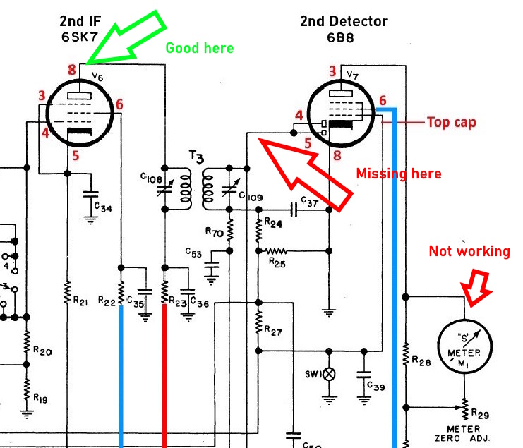
Decided all the components between V6 and V7 are suspect.
Recapping One is probably a good idea. Started with V6 and V7.
Then decided all the components between V9 and V10 are suspect.
Recapping Two V9 and V10 plus a new S meter pot is probably a good idea too.
Page: /5th_radio_resurrection/Resurrect.shtml
Last modified: Monday, 1 Jun 2026